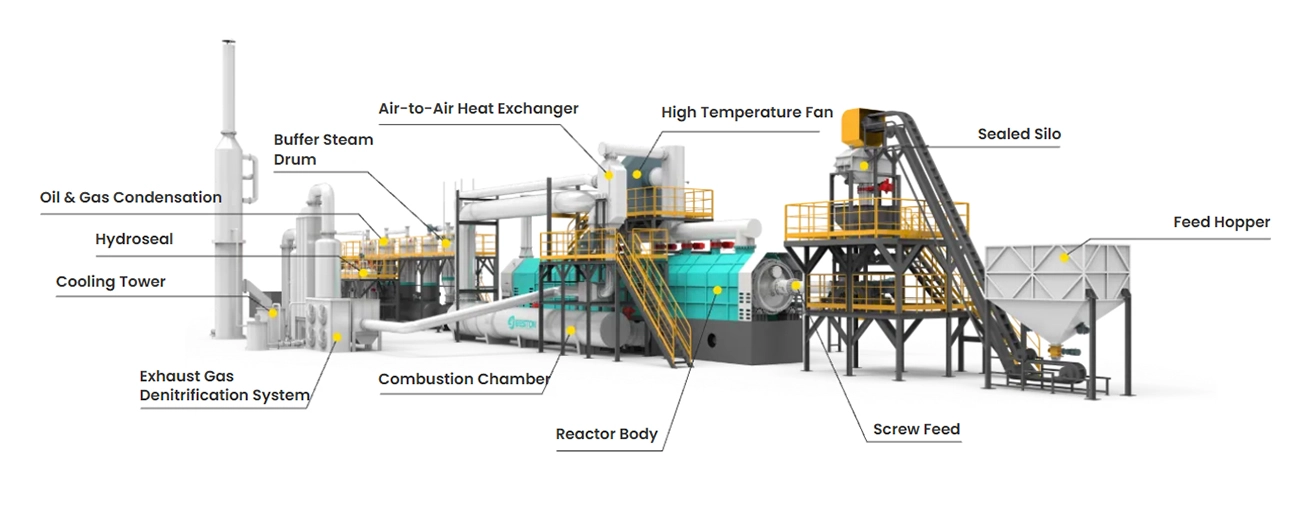
A pyrolysis plant’s main components work to heat materials without oxygen, producing oils, gases, and solids. The components typically include a feeding system, a central pyrolysis reactor, a condensing system, a gas handling system, a solid discharging system, and an electronic control system, all working together to manage the breakdown, collection, and purification of products.
01 Feeding System: Diverse Solutions
The feeding system conveys raw materials into the reactor of a pyrolysis plant. Based on project scale and labor costs, three main feeding methods are available: manual feeding, hydraulic feeding, and screw feeding. Belt conveyors are frequently used alongside these systems to improve feeding efficiency.

Solution 1: Manual Feeding
Operators manually lift and move raw materials to load them into the pyrolysis reactor.
- High manual labor intensity;
- No complex material pretreatment required;
- Can be used together with belt conveyors or forklifts.
Solution 2: Hydraulic Feeding
The hydraulic system generates strong thrust to densely pack the materials into the reactor.
- Low labor intensity;
- Accepts whole tires, tire shreds, and various crushed materials;
- Easy to operate and move.
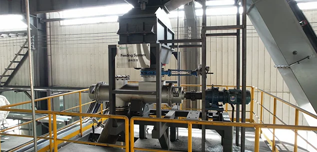
Solution 3: Screw Feeding
The screw feeder uses a motor to drive the screw and convey materials into the reactor.
- Low labor intensity;
- Particularly suitable for continuous operation;
- Easy to operate and move;
- Note: Feedstock pretreatment is required to ensure smooth feeding.
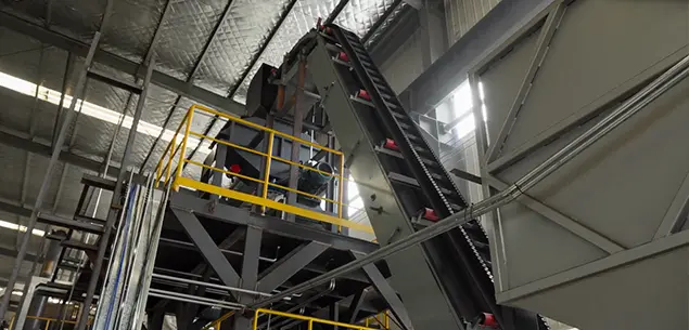
Auxiliary: Belt Conveyor
The belt conveyor can be used with the three feeding methods mentioned above to enhance feeding efficiency.
- Structure: A mechanical assembly comprising a high-strength conveyor belt, a supporting metal frame, multiple idlers, a tensioning device, motors and reducers.
- Function: Continuous long-distance material transportation to the feeding system. It features a simple structure that is easy to maintain.
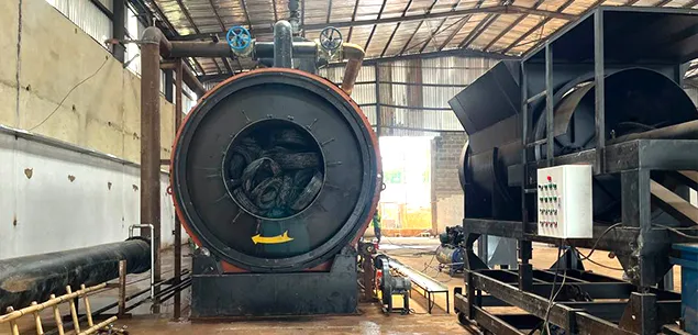
02 Reactor System: Core Component
The pyrolysis reactor system is the functional heart of a plastic pyrolysis plant. Its primary objective is to provide a controlled environment—oxygen-free, heated, and continuously agitated—to facilitate the thermal cracking of polymer chains in raw materials.
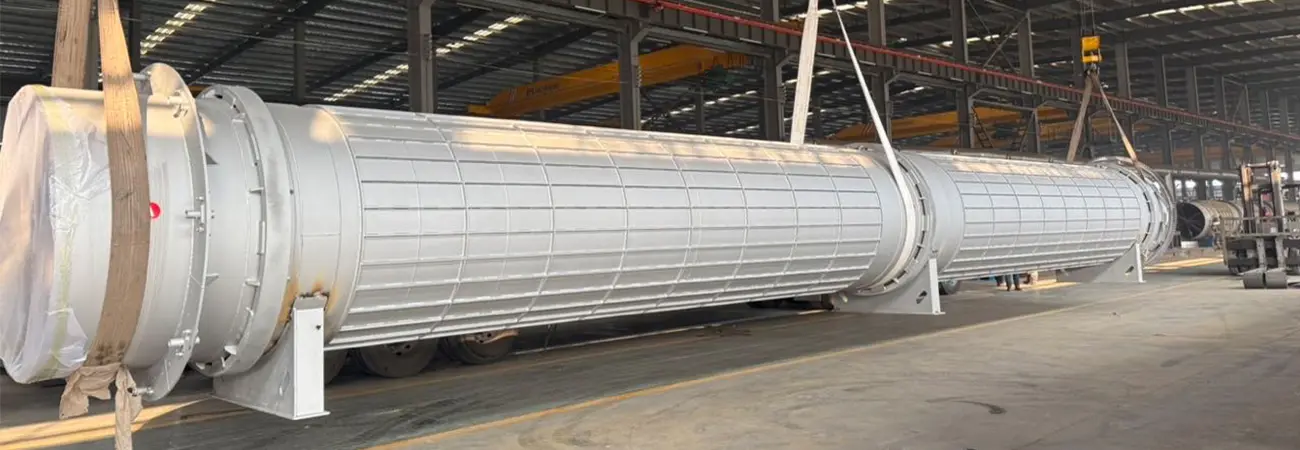
Pyrolysis Reactor
- Structure: A horizontal, cylindrical pressure vessel typically fabricated from specialized boiler-grade steel (such as 304/310S Stainless steel) to withstand high temperatures. It features internal lifting plates or spiral flights and is mounted on riding rings that interface with support rollers. The entire vessel is hermetically sealed to maintain a strictly anaerobic environment.
- Function: Thermal decomposition and material agitation. As the reactor rotates, the internal structures ensure constant material movement and uniform heat absorption. Once the materials reach the cracking temperature, the molecular chains break down, transforming solid waste into gaseous oil gas and solid product.
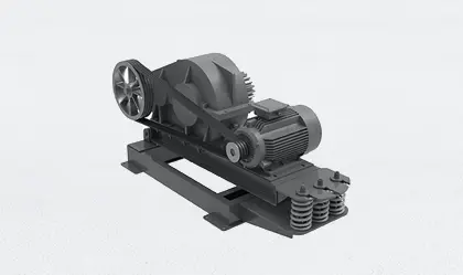
Driving System
- Structure: Consists of an electric motor, a reduction gearbox, and a transmission gear mechanism.
- Function: Provides the mechanical torque required for the reactor’s rotation. By precisely controlling the Rotations Per Minute (RPM), it ensures that the material residence time meets process requirements and promotes uniform heat distribution through constant agitation.
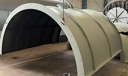
Casing
- Structure: A stationary outer enclosure surrounding the rotating reactor, lined with high-density refractory materials such as ceramic fiber, rock wool, or refractory bricks.
- Function: Acts as a thermal barrier to minimize radiant heat loss to the atmosphere, maintaining a stable internal process temperature. It also serves as a flue gas channel, directing hot air from the combustion chamber to envelop the reactor surface for maximized heat transfer.
Base
- Structure: A reinforced steel framework that serves as the stationary mounting platform for the entire rotating reactor, lined with refractory materials (such as firebricks or castables).
- Function: It provides structural support for the reactor’s total weight. It also serves as the heat generation zone where fuel combustion transfers thermal energy via radiation and convection.
03 Condensing System: Oil & Gas Separator
The condensing system is the critical stage where high-temperature oil gas is cooled and converted into liquid fuel. By utilizing a series of high-efficiency heat exchangers and safety vessels, it rapidly reduces the gas temperature to ensure maximum oil yield and process safety.
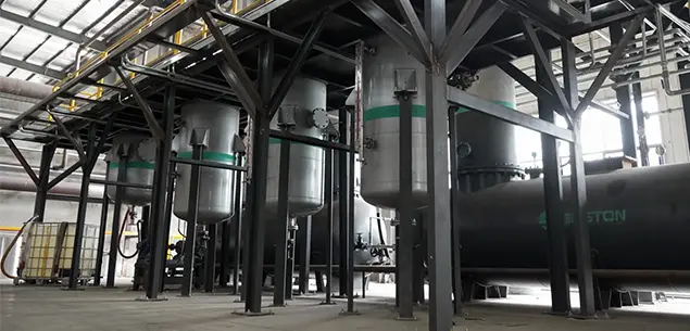
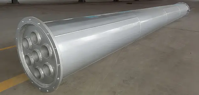
Oil Gas Condenser
- Structure: An industrial heat exchanger, typically shell-and-tube type, featuring a network of internal cooling water pipes.
- Function: Phase-change cooling. It facilitates heat exchange between the hot oil gas and circulating cooling water, rapidly condensing the hot oil gas into liquid fuel oil.
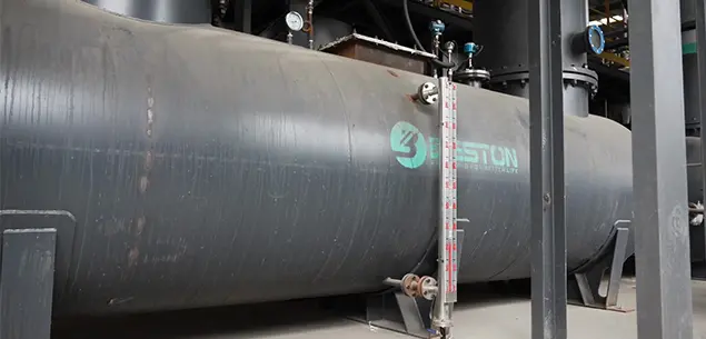
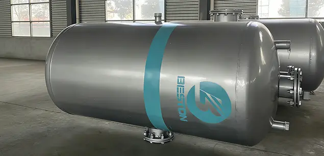
Oil Storage Tank
- Structure: A sealed horizontal or vertical metal vessel connected to the condenser outlets.
- Function: Storage and buffer. It collects and stores the liquefied fuel oil via gravity, usually equipped with level gauges to monitor production volume.
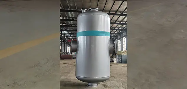
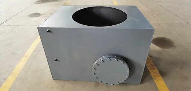
Manifold
- Structure: A large-diameter pressure vessel positioned between the reactor outlet and the condensers.
- Function: Primary sedimentation and distribution. It reduces oil gas velocity to separate heavy particles and light particles of oil gas. There is a draining valve at the bottom of the manifold to drain residue and a tube on the top to discharge oil gas to the condenser.
Hydroseal
- Structure: A water-filled safety vessel where non-condensable combustible gases are bubbled through a submerged pipe.
- Function: Flashback protection and purification. It prevents gas backflow and fire risk by utilizing water pressure and pre-cleans the gas by removing acidic components and trace impurities.
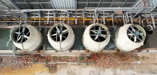
Cooling Tower
- Structure: A large vertical structure featuring a powerful top-mounted axial fan, internal cooling fill/packing materials, and a water collection basin at the bottom.
- Function: Thermal dissipation and water recirculation. It utilizes evaporative cooling to lower the temperature of the return water from condensers, providing a continuous supply of chilled water to maintain the oil gas liquefaction process.
04 Dedusting System: Environmental Compliance Guarantee
The dedusting system collects and purifies the flue gas from the reactor to achieve standard emissions. The smoke and dust produced in combustion chamber goes through flue condenser, which reduces the temperature to about 140 degrees; the cooled smoke and dust was introduced to the water tank by the induced draft fan, passes through the impacting of water, then through the adsorption of Bayer magnetic, water spray, to make the temperature below 100 degrees; then discharge the smoke through the chimney, in line with the emission of European standards.
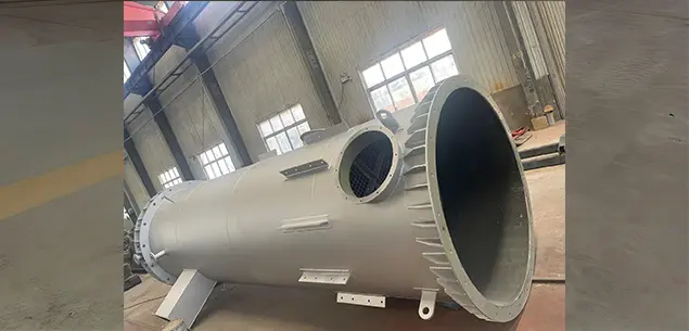
Flue Gas Condenser
- Structure: Similar in appearance to a spray tower but filled with specialized corrosion-resistant packing materials (such as Raschig rings) to increase the gas-liquid contact area.
- Function: Chemical neutralization. By circulating an alkaline solution (e.g., NaOH), it chemically reacts with and neutralizes acidic pollutants in the flue gas, ensuring that emission levels comply with local regulatory requirements.
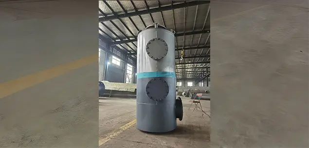
Spray Tower (Scrubbing Tower)
- Structure: A tall vertical cylindrical tower equipped with multiple levels of atomizing nozzles and a circulating water tank at the base.
- Function: Scrubbing and cooling. As flue gas enters from the bottom, it makes counter-current contact with the descending water mist. This process utilizes physical interception and chemical absorption to remove dust particles, acidic gases (such as SO2), and a portion of the thermal energy.
Desulfurization Tower
- Structure: Located at the vertical junction between the two screw conveyor stages (distinguishable by visible flange connections and red-wheeled actuators).
- Function: Acts as the core air-lock seal. Utilizing the zero-leakage characteristics of ball valves, these valves open and close alternately during discharge to ensure the reactor remains isolated from the external atmosphere. This is a critical safety component to prevent oxygen backflow into the high-temperature reactor.
Atomization Water Tank
- The water tank provides water for the spray system of the spray tower and facilitates water recycling.
Chimney
- The chimney is a ventilation structure. It is typically vertical or as close to vertical as possible to ensure the smooth flow of flue gas and its discharge into the air.
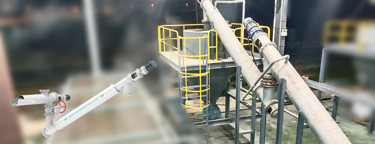
05 Discharging System: Carbon Black Collector
The discharging system discharges carbon black from the reactor through an internal screw. It achieves full automation, cleanliness, and pollution-free operation, saving time and effort. Components include:
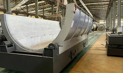
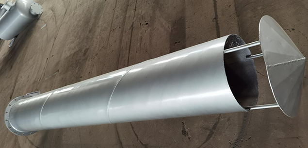
Screw Conveyors/Discharging screw
- Structure: Mainly includes a drive device, spiral shaft, spiral blades, and spiral casing.
- Function: Responsible for the mechanical displacement of solid products (carbon black). The first-stage screw extracts material from the reactor, while the second-stage continues the outward transport. This dual-stage design extends the transport path, utilizing the material’s self-weight to facilitate a preliminary material seal.
Water Cooling Jackets
- Structure: The thickened sections of the screw conveyor’s outer casing (the white piping sections), featuring internal cooling water circulation channels equipped with inlet and outlet ports.
- Function: Facilitates heat exchange and cooling. Since carbon black is extremely hot when exiting the reactor, the water jacket uses thermal conduction to rapidly cool the material to a safe discharge temperature (typically below 50℃), preventing spontaneous combustion at the outlet.
High-temperature Ball Valves
- Structure: Located at the vertical junction between the two screw conveyor stages (distinguishable by visible flange connections and red-wheeled actuators).
- Function: Acts as the core air-lock seal. Utilizing the zero-leakage characteristics of ball valves, these valves open and close alternately during discharge to ensure the reactor remains isolated from the external atmosphere. This is a critical safety component to prevent oxygen backflow into the high-temperature reactor.
Drive Motors
- Structure: Cyan-colored components located at the ends of both screw conveyor stages, typically equipped with industrial-grade gear reducers.
- Function: Provides rotational power. The independent motor design allows for individual speed control of each stage to match the reactor’s discharge rate, ensuring that material does not accumulate at transition points or corners.
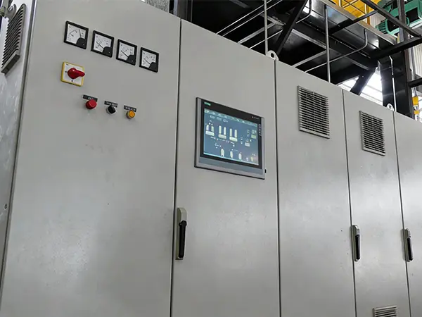
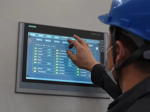
06 Electronic Control System: Control Center
Electrical control cabinet: It controls the switches and operation of various motors within the tyre pyrolysis plant. It displays the temperature and pressure of key components, providing data for production operations.
07 Other Accessories
In addition to the mentioned critical components, the whole set of oil sludge pyrolysis plant also involves several other accessories, such as
- Burner: mixes fuel and air in a controlled manner to provide the initial thermal energy for the reactor;
- Blower: conveying air to the combustion chamber to ignite combustible gases to heat the reaction vessel;
- Burning room: burns off excess combustible gas to enhance safety and reduce pollution;
- Airbag: stores the combustible gas produced by the pyrolysis equipment to provide fuel for subsequent production;
- etc.


